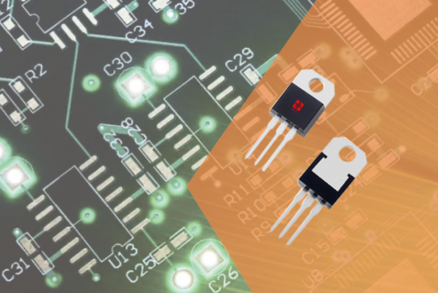
ESD electrostatic discharge overview
When a charged object comes into contact with another object at a different potential, the charges between the two objects equalize. The voltage v(t) and current i(t) transients when this occurs are shown below. The amplitude and waveform of the transient depend on the voltage difference and total impedance in the current path. The pulses will be induced and may produce signals that may affect nearby electronic circuits. If the discharge current through the product attempts to take a path that includes an air gap, a secondary discharge may occur within the device. The voltage across the gap increases until the gap fails.
Some steps to avoid ESD issues in your design:
a) Select a circuit configuration that is unresponsive to short transients.
b) Lay out the PCB pattern to minimize induced voltages at critical nodes.
c) Prevent unavoidable discharge transients from coupling into circuits and cables.
d) Design enclosures wherever possible to prevent emissions from occurring.
ESD testing complies with IEC61000-4-2
IEC61000-4-2 is the standard for immunity ESD testing. It applies a defined current waveform at a specified voltage level from a handheld generator called an ESD gun. It uses a capacitor supplied by a high-voltage power supply, whose charged voltage is discharged through a series impedance through the contacts to ground. Two discharge methods are used. They are contact discharge and air discharge.
ESD Test-Contact Discharge
In the contact discharge method, stress can be applied directly to the EUT or to the coupling plane adjacent to the EUT. Before each test pulse, the capacitor is charged to the required level, but its voltage is held at the generator’s probe via a vacuum relay. Apply the probe to an appropriately chosen point on the EUT or coupling plane. The generator is then triggered, causing the relay contacts to close and the capacitor voltage to be applied to the EUT through the probe. This creates a current pulse when voltage discharges through the combined series impedance of the generator, EUT and ground plane. Repeat the movement the desired number of times with appropriate polarity and level in each position.
ESD test-air discharge
The same generator is used for the air discharge method, but with a rounded rather than pointed probe tip. The capacitor is charged to the desired level as before, but the voltage is now continuously applied to the probe, which is located away from the EUT. For each test pulse, the tip is subtly raised to a selected point on the EUT until it makes contact. Just before this happens, the air gap between the tip and the EUT will breakdown and the discharge current will flow, limited as mentioned before by the combined series impedance of the generator, air gap, EUT and return path. Again, repeat the movement the desired number of times with appropriate polarity and level in each position.
Electrostatic discharge ESD test layout
ESD pulses have sub-nanosecond rise times, so RF layout precautions are critical.
1. The test must recreate the actual fast rise time found as this is an important parameter that determines the path of the discharge through the EUT and the response of the EUT itself. The Ground Reference Plane (GRP) is an integral part of the setup to which the return lead of the generator must be well connected as this connection forms part of the current return path.
2. The indirect discharge part of the test uses two other planes different from GRP, called horizontal coupling plane (HCP) and vertical coupling plane (VCP). The discharges from these aircraft simulate the stresses generated from real-life radiation fields emitted to nearby objects.
3. Each coupling plane is connected to the GRP via resistive leads to ensure any charge flows out within a few microseconds. The construction of these leads is critical: each end should be close to a resistor so that the length of lead between them is isolated from the connection and stray coupling from it is neutralized.
4. Although the power rating is not important, the resistor itself should be able to withstand high pulse dV/dt without damage, so the carbon composition type is suitable.
5. For ESD events of tens of nanoseconds, the plane carries the full stress voltage, which is capacitively coupled to the EUT. Any stray capacitance from the plane to objects other than the EUT will modify the plane’s voltage and current waveforms, thereby modifying the applied stress.
6. Therefore, it is important to maintain at least 1 meter of clear space around the EUT, which means the tabletop setup has some separation from walls or other objects.
7. Likewise, separation from the VCP to the EUT is specified as 10cm; even small changes in this distance can cause large changes in coupling to the EUT, so convenient methods of controlling it, such as plastic 10cm spacers on planar surfaces, is helpful.
More information
Semiware provides a full range of ESD electrostatic protection devices and provides customers with a complete ESD testing environment. We have EMC electromagnetic compatibility laboratories and excellent EMC engineers at home and abroad to provide you with services at any time. For more information, please visit the Semiware page: https://semiware.com/
About Semiware
Semiware has a comprehensive product lineup of overvoltage protection device families. The company leverages its technology in the semiconductor field and application background in end products to serve customers in the electronics, automotive and industrial markets. If you have technical questions, please contact the technical support team as follows:
Email: fae01@semiware.com;
Phone: 86-21-3463-7654;
Toll-free technical support hotline: 400-021-5756;
For more information, please visit semiware official website: https://semiware.com

 Automotive TVSs
 General TVS Diodes
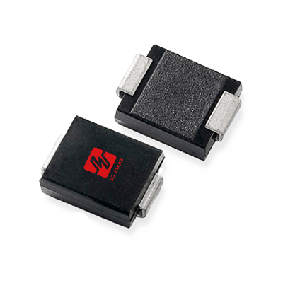 High Reliability TVSs
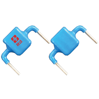 High Current TVSs
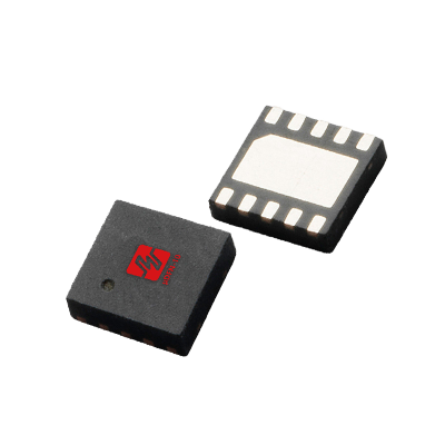 Automotive ESDs
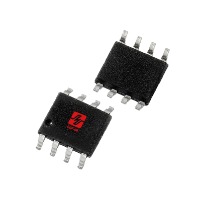 TVS Diodes Array
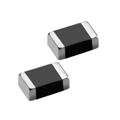 MLVs
MLVs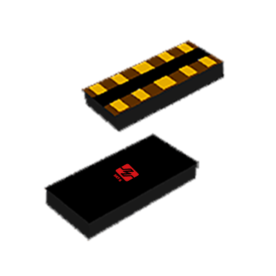 Polymers
 High Reliability
 General Thyritors
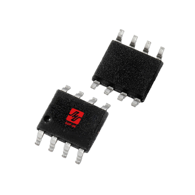 Programmable Series
 Automotive PLEDs
 Pled Protectors
 General Gas Tubes
 Automotive GDTs
 Glass Discharge Tubes
 General Varistors
 Sensitive SCRs
 SCRs
SCRs Triacs
 4-Quadrant Triacs
 Small Signal Mosfets
 Power Mosfets
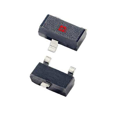 Transistors
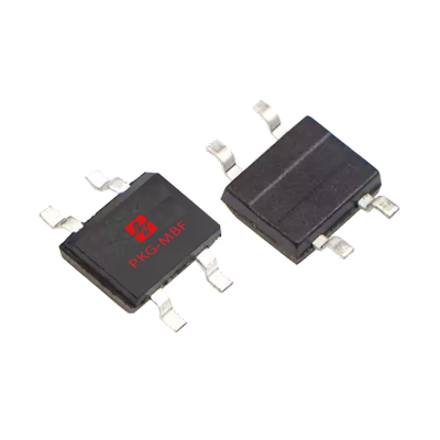 Bridge Rectifiers
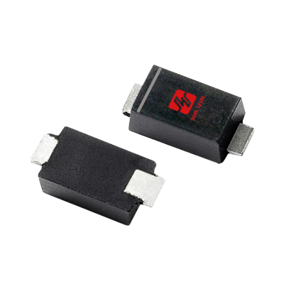 Schottky Rectifiers
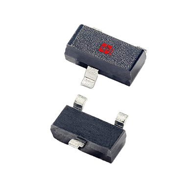 Switching Diodes
 Fast Recovery Diodes
 Rectifier Diodes
 Fast Recovery Diodes
 PTC
PTC Energy Storage
 Vehicle Adapter
 Media Hub
 Interior Light
 Head Lighting
 DC Charger
 PTC
PTC AC Charger
 BMS
BMS ADAS
ADAS BCM
BCM xDSL
xDSL Outdoor AP
 Set-top Box
 PBX
PBX RRU
RRU BBU
BBU Power Supply
 Small Cell
 Cellular Base Station
 IP Camera
 Security Camera
 NVR
NVR DVR
DVR Two-wheeler locator
 POS
POS VR
VR UAV
UAV E-Bike
 PC
PC Pad
Pad Smart Lock
 Mobile Phone
 Smart Watch
 E-Cigarette
 TWS
TWS PV Inverter
 Energy Storage
 DC-DC Module
 Power Bank
 Fast Charging
 Adapter
 ECG monitor
 Sphygmomanometer
 Electronic Scale
 Radiography
 Exergen
 Blood Glucose Meter
 DC Motor
 PLC
PLC Smart Metering
 Sensor
 Power Line Carrier
 Electricity Meter
 Elevator Call Board
 Traffic Lighting
 Solar Lighting
 Smart Lamps
 Led Lighting
 StreetLight Controller
 Dishwasher
 Sweeping Robot
 Smart TV
 Washing Machine
 Smart Speaker
 Coffee Maker
 Buttons/Switches
 LIN
LIN DC12V-P5a
 NFC
NFC MIC
MIC Audio
Audio GPS
GPS RJ11
RJ11 POE-10G-6KV
 Type-C
 VGA
VGA USB2.0-Dual
 RS232-ESD
 HDMI
HDMI eSATA
eSATA USB3.0
 AC220V-5KA
 Semiware's over 300 interface protection solutions cover automotive electronics, industrial control, consumer electronics, and other industry sectors.
 To become an excellent comprehensive service provider of circuit protection solutions.
 To become an excellent comprehensive service provider of circuit protection solutions.

 简体中文
简体中文


