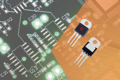
1. The difference between one-way thyristor and two-way thyristor
SCRs are divided into unidirectional and bidirectional, with different symbols. One-way thyristors have three PN junctions. Two electrodes are drawn from the outermost P electrode and N electrode, which are called anode and cathode respectively. The middle one The P pole leads to a control pole. , the unidirectional thyristor has its unique characteristics: it will not conduct when the anode is connected to reverse voltage or when the anode is connected to forward voltage but no voltage is applied to the control electrode, and when the anode and control electrode are connected to forward voltage at the same time, it will will become conductive. Once it is turned on, the control voltage loses its control effect. It will always be on regardless of whether there is a control voltage or the polarity of the control voltage. To turn off, the anode voltage can only be reduced to a certain critical value or reversed. Most of the pins of triacs are arranged from left to right in the order of T1, T2, and G (when the electrode pins are facing downward, facing the side with characters). When the size or time of the trigger pulse applied to the control electrode G changes, the size of its conduction current can be changed. The difference from the one-way thyristor is that when the polarity of the trigger pulse on the G pole of the two-way thyristor changes, its conduction direction changes with the change of polarity, thus being able to control the AC load. The unidirectional thyristor can only conduct in one direction from the anode to the cathode after being triggered, so the thyristor can be divided into single and bidirectional. SCRs are commonly used in electronic manufacturing, such as MCR-100 for one-way and TLC336 for two-way.
2. One-way thyristor detection
Select the resistance Rx1 level of the multimeter, use the red and black test pens to measure the forward and reverse resistance between any two pins until you find a pair of pins with a reading of tens of ohms. At this time, the pin connected by the black pen is the control pole G, and the red pen is connected The pin is the cathode K, and the other empty pin is the anode A. At this time, connect the black test lead to the judged anode A, and the red test lead is still connected to the cathode K. The multimeter pointer should not move at this time. Use a short wire to instantly short-circuit anode A and control electrode G. At this time, the multimeter pointer should deflect to the right, and the resistance reading is about 10 ohms. For example, when anode A is connected to a black test lead and cathode K is connected to a red test lead, the multimeter pointer will deflect, indicating that The one-way thyristor has been damaged due to breakdown.
3. Bidirectional thyristor detection
Use the resistance Rx1 setting of the multimeter and use the red and black test leads to measure the positive and negative resistance of any two pins respectively. As a result, the two sets of readings are infinity. If a group is tens of ohms, the two pins of the red and black test leads connected to the group are the first anode A1 and the control electrode G, and the other empty pin is the second anode A2. After determining the A and G poles, carefully measure The forward and reverse resistance between A1 and G. The pin connected to the black test lead for the measurement with a relatively small reading is the first anode A1, and the pin connected to the red test lead is the control electrode G. Connect the black test lead to determine The second anode A2, the red test lead is connected to the first anode A1. At this time, the multimeter pointer should not deflect and the resistance value is infinite. Then use a short wire to instantly short-circuit the A2 and G poles, and add a forward trigger voltage to the G pole. The resistance between A2 and A1 is about 10 ohms. Then disconnect the A2 and G pole short wires, and the multimeter reading should remain around 10 ohms. Interchange the red and black test lead connections. The red test lead is connected to the second anode A2, and the black test lead is connected to the first anode A1. Similarly, the multimeter pointer should not deflect and the resistance value is infinite. Use a short wire to momentarily short-circuit the A2 and G electrodes again, and apply a negative trigger voltage to the G electrode. The resistance between A1 and A2 is also about 10 ohms. Then disconnect the short wire between A2 and G. The multimeter reading should remain unchanged at about 10 ohms. Complying with the above rules, it means that the tested triac is not damaged and the polarity of the three pins is judged correctly.
4. Application of thyristor
SCR is the abbreviation of Silicon Controlled Rectifier. It is a high-power semiconductor device with a four-layer structure with three PN junctions, also called a thyristor. It has the characteristics of small size, relatively simple structure, and strong functions, and is one of the more commonly used semiconductor devices. This device is widely used in various electronic equipment and electronic products, and is often used for controllable rectification, inverter, frequency conversion, voltage regulation, contactless switch, etc. In household appliances, dimming lamps, speed-adjustable fans, air conditioners, televisions, refrigerators, washing machines, cameras, combination speakers, sound and light circuits, timing controllers, toy devices, radio remote controls, cameras and industrial controls are all widely used. silicon controlled device.
About Semiware
Semiware has a complete product lineup of silicon controlled devices, with a total number of standardized products of 800+; the company relies on its R&D technology in the semiconductor field and application technology of end products to provide services to global customers in the electronics, automotive and industrial markets. For more information about related products, please visit https://semiware.com/product-line/scr-triac/

 Automotive TVSs
 General TVS Diodes
 High Reliability TVSs
 High Current TVSs
 Automotive ESDs
 TVS Diodes Array
 MLVs
MLVs Polymers
 High Reliability
 General Thyritors
 Programmable Series
 Automotive PLEDs
 Pled Protectors
 General Gas Tubes
 Automotive GDTs
 Glass Discharge Tubes
 General Varistors
 Sensitive SCRs
 SCRs
SCRs Triacs
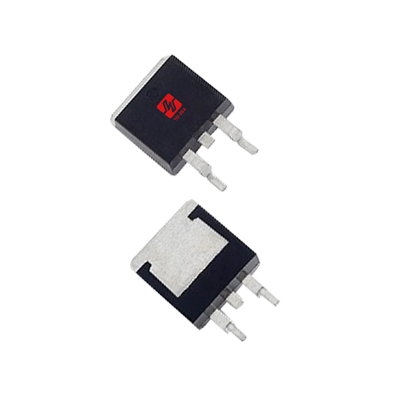 4-Quadrant Triacs
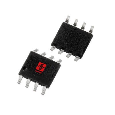 Small Signal Mosfets
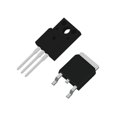 Power Mosfets
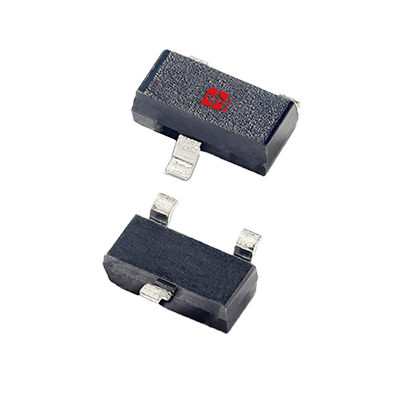 Transistors
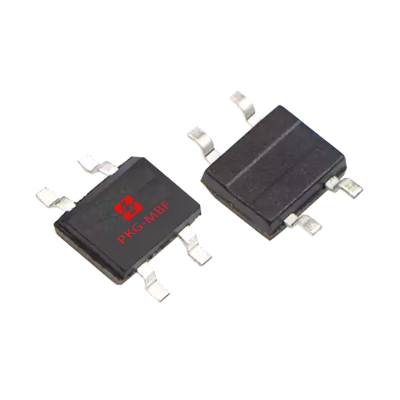 Bridge Rectifiers
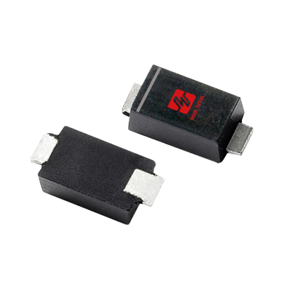 Schottky Rectifiers
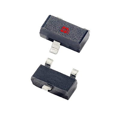 Switching Diodes
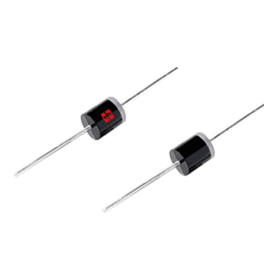 Fast Recovery Diodes
 Rectifier Diodes
 Fast Recovery Diodes
 PTC
PTC Energy Storage
 Vehicle Adapter
 Media Hub
 Interior Light
 Head Lighting
 DC Charger
 PTC
PTC AC Charger
 BMS
BMS ADAS
ADAS BCM
BCM xDSL
xDSL Outdoor AP
 Set-top Box
 PBX
PBX RRU
RRU BBU
BBU Power Supply
 Small Cell
 Cellular Base Station
 IP Camera
 Security Camera
 NVR
NVR DVR
DVR Two-wheeler locator
 POS
POS VR
VR UAV
UAV E-Bike
 PC
PC Pad
Pad Smart Lock
 Mobile Phone
 Smart Watch
 E-Cigarette
 TWS
TWS PV Inverter
 Energy Storage
 DC-DC Module
 Power Bank
 Fast Charging
 Adapter
 ECG monitor
 Sphygmomanometer
 Electronic Scale
 Radiography
 Exergen
 Blood Glucose Meter
 DC Motor
 PLC
PLC Smart Metering
 Sensor
 Power Line Carrier
 Electricity Meter
 Elevator Call Board
 Traffic Lighting
 Solar Lighting
 Smart Lamps
 Led Lighting
 StreetLight Controller
 Dishwasher
 Sweeping Robot
 Smart TV
 Washing Machine
 Smart Speaker
 Coffee Maker
 Buttons/Switches
 LIN
LIN DC12V-P5a
 NFC
NFC MIC
MIC Audio
Audio GPS
GPS RJ11
RJ11 POE-10G-6KV
 Type-C
 VGA
VGA USB2.0-Dual
 RS232-ESD
 HDMI
HDMI eSATA
eSATA USB3.0
 AC220V-5KA
 Semiware's over 300 interface protection solutions cover automotive electronics, industrial control, consumer electronics, and other industry sectors.
 To become an excellent comprehensive service provider of circuit protection solutions.
 To become an excellent comprehensive service provider of circuit protection solutions.

 简体中文
简体中文
