The automotive environment is challenging for electronics. Transient spikes, noise and discharges
are common, and it is necessary to protect sensitive semiconductor devices from damage. This is
done using Transient Voltage Suppressor (TVS) devices. This article will give an understanding of the
characteristics of TVS devices, and then show where and how some might be used in a vehicle.
TVS Characteristics
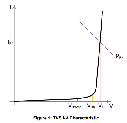
The Reverse Standoff Voltage, also known as the Reverse Working Voltage (VRWM) is the specified
voltage at which the device will draw only a very small leakage current (of the order of a few µA); this
can be as low as 3.3V. It is allowable to select a device with a VRWM equal to the typical working
voltage of the circuit – For example, on a 3.3V microprocessor input or power supply you can choose
a protection device with a VRWM of 3.3V. VRWM is not a measured figure – it is a nominal figure at
which a maximum current is measured.
Reverse Breakdown Voltage (VBR) is measured at the point where the device begins to conduct
strongly, at a current of 1-10mA. VBR can vary over a wide tolerance – it may even overlap with
adjacent values in the range of TVS devices. This is a guide to where the knee of the I-V
characteristic is. It is important to consider the minimum VBR value against the tolerance of the circuit
you are protecting so that the TVS does not conduct at the maximum tolerance of supply voltage.
Maximum Clamping Voltage (VC) and Maximum Peak Current (IPP) are measured from the I-V
characteristic at the point where the line intersects the Peak Pulse Power limit (PPK) of the device.
Directionality
An important aspect of TVS devices is directionality. The most basic type of TVS is unidirectional:
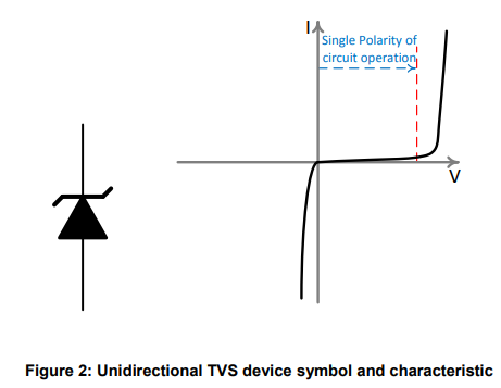
This type of device is used where the operating area of the circuit to be protected is always positive,
for example 0 to +5V. The device will protect against positive and negative transients (immediately,
as forward conduction in the device).
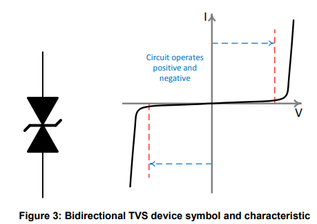
Where the circuit has both positive and negative operation, such as a split rail audio system or a
differential signalling scheme, a bidirectional TVS provides protection for transients that go beyond
the safe operating area – either positive or negative.
Bidirectional TVS can be either symmetrical (VBR is the same in both directions) or asymmetrical (VBR
is greater in one direction than the other direction).
Why are Reverse Standoff Voltage and Reverse Breakdown Voltage positive?
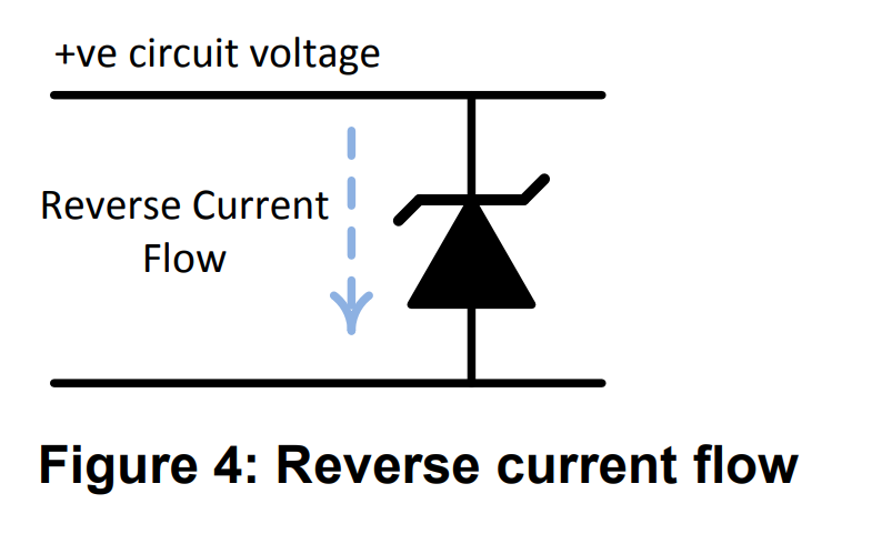
VRWM, VBR and VC are positive, like the operating voltages of the
circuit being protected – the voltage that transients will be limited to.
This is the convention used across the industry, even though the
device is being used in the reverse direction.
Zener TVS compared to Zener Diode
Often the same symbols are used for Zener TVS devices as for Zener Diodes, and it may give rise to
questions about the differences between the two. Both devices rely on the Zener breakdown effect
and have I-V characteristics that look very similar. What is the difference?
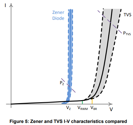
Although they appear similar, a closer look at the I-V characteristics in Figure 5 immediately shows
the differences. The Zener Diode (blue trace, Vz) has a much sharper knee, steeper slope and tighter
voltage tolerance (dashed lines and shaded region) than a TVS device.
These differences come from design and optimization – the purpose of a Zener Diode is to provide an
accurate voltage clamp within a signal circuit, or as a reference or regulator. A Zener diode will
normally have current flowing through it either constantly or for longer periods of time (several
seconds in a clamp application) The TVS exists to handle the energy from spikes and transients that
might otherwise cause damage to sensitive components. The TVS device is designed to absorb a
large amount of energy in a very short time (nanoseconds to milliseconds). The peak currents can be
very large but not for continuous operation. The accuracy of a TVS is less important than the
accuracy of a Zener Diode.
During normal circuit operation the TVS device should not conduct other than leakage.
Power Rating
On first inspection the power ratings of TVS devices seem extraordinarily high, but the power rating is
a pulse rating. A TVS device is not intended for continuous operation.
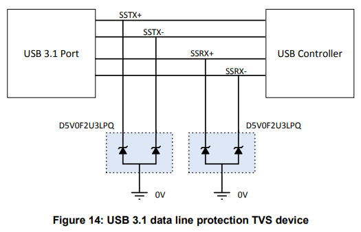
A typical pulse waveform is shown in Figure 6. Two common waveforms are used, with different
values of t1 and t2. Those waveforms are known as 8/20 (t1 = 8µs, t2 = 20µs, defined in IEC61000-4-
5) and 10/1000 (t1 = 10µs, t2 = 1000µs, defined in IEC61643-321). Note that t2 is elapsed time from
0, not t1.
The 8/20 pulse shows how the device will handle events like ESD discharge and lightning strikes.
The 10/1000 pulse shows how the device will handle slower speed higher energy events like power
supply surges. In automotive applications, these events are likely to come from the alternator and
inductive loads.
A TVS device may have two different power ratings, one relating to each of these pulses, and they
are quite different. It is much clearer why that is the case if the two pulses are overlaid to scale as
shown in figure 7.
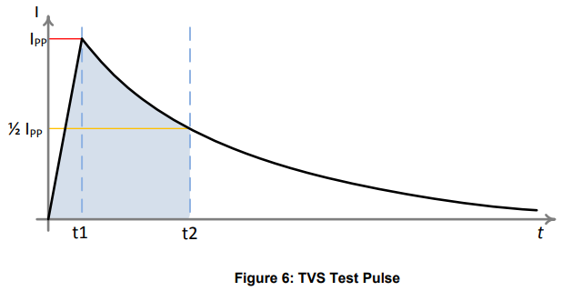
The published power figure is VC × IPP. VC varies with IPP – therefore the lower IPP of the 10/1000
pulse also gives a lower VC, again reducing the Peak Power figure.
For the shorter time duration spike on the 8/20 pulse (Blue trace), the device can handle a much
higher current. The important thing is the energy of the pulse, represented by the area under the
curve (shaded blue area, 0-20µs). Compare to the 10/1000 pulse (Orange trace) and it’s clear that
the area under the curve (shaded orange area, 0-1000µs) is much greater, limiting the peak figure.
The easiest way to think about this is that the device has an internal capacity to absorb a set amount
of energy as heat. That can happen at very high rates for a very short time, or lower rates for a longer
time.
TVS Products in an Automotive System
In a vehicle there are several specific areas in which TVS devices might be used, protecting against
somewhat different threats.
The 12V system of a traditional car is powered from the Alternator, and its output is rectified and
regulated to provide the nominal 12V to charge the battery and provide power to accessories.
Because both the generation and some of the loads (e.g. window motors, wiper motors, seat motors,
etc.) are inductive, there can be significant spikes and dips on the 12V power system as loads are
connected, disconnected, stall, etc. Of course, cranking and ignition of an Internal Combustion
Engine also presents a very significant and difficult load. This rail also experiences ESD discharges
and noise from many systems like ignition coils, injectors and HID lamps.
To protect the systems within the vehicle there are multiple levels of TVS devices. There are very
large TVS devices fitted around the alternator and regulator (marked 1 in figure 10) to absorb highenergy events like load dump, field decay, etc.
Each electronic module attached to the 12V power will have its own TVS (marked 2 in figure 10) and
reverse polarity protection. The data buses that connect these various modules are not directly
vulnerable to the power rail threats, but they will be liable to pick up noise and ESD discharges, which
connect to the relatively sensitive low-voltage microprocessors. These buses have protection devices
also (marked 3 in figure 10).
Automotive Power Rail Pulses
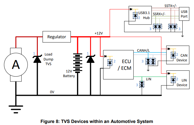
The standards ISO 7637-2 and ISO 16750 set out a series of defined pulses on the 12V power rail
that must be dealt with by the system. Figure 9 gives a sense of these pulses – their magnitude and
what they are meant to model. (Note: not to scale)
It is important to consider the system as a whole – for example, there may be a main Load Dump
TVS which is very large and placed close to the alternator. This will absorb most of the energy in a
load dump event, and for this reason there is an option to test automotive modules with the remaining
load dump energy that would reach them:
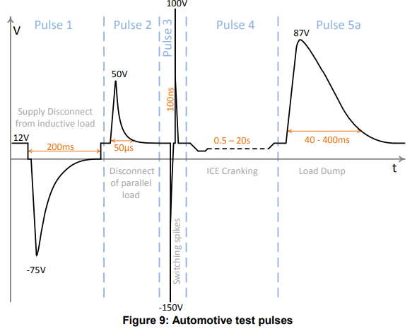
The magnitude of pulse 5b is determined by the customer, by defining the voltage of the main load
dump TVS.
Pulses 1 and 5 in Figure 9 have a significantly longer time duration than the 10/1000µs test pulse
described on page 4. TVS products in automotive applications therefore will require greater power
handling than those in a non-automotive environment.
Power Rail TVS
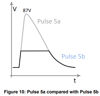
Each module within a vehicle will tend to have both reverse battery polarity protection (shown here as
a diode, but often implemented as a MOSFET) and a TVS device to protect that module from
transients. A TVS device fitted to the power input of an ECU must be rugged and capable of
dissipating a significant energy, although it will not be trying to handle the entire energy of a load
dump event, for example. Industry-standard devices such as TPSMCJ28CA, packaged in the 1.5kW
(10/1000µs) rated SMC package, are typically deployed to protect powerlines.
However, the drive toward high-power dissipation and reduced footprint has resulted in the
development of TVS in the small form factor thermally efficient package.
CAN bus and FlexRay
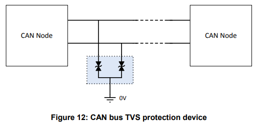
Modern vehicles carry a lot of data over buses such as CAN and FlexRay. These buses can carry
safety-critical information so they must not only be rugged but also reliable. It is important that these
buses are protected from transients and noise and are protected in a way that does not reduce the
bandwidth of the signal. These buses are more likely to encounter low-energy noise and ESD than
high-energy transients like load dump. For this reason, smaller, lower power protection devices are
appropriate.
CAN bus and FlexRay are differential buses, and so they require dual bidirectional TVS to protect
both of the data lines. They should be low capacitance to maintain signal integrity.
CAN bus is not necessarily ground referenced – different nodes in the vehicle may experience
different ground voltages. The TVS device can limit both common and differential mode spikes to
protect the CAN devices.
LIN bus
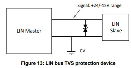
In simple physical terms the LIN bus is a 2 wire bus comprising of signal and ground wires. The
signal can potentially be between +24V and -15V (due to ground level variance around a vehicle), so
an asymmetrical bidirectional device is required.
The TPSE23T20B24LB is dual bidirectional parts suitable for
CAN and FlexRay respectively. The PESD1LIN is a compact 2-terminal asymmetric TVS
device suited to LIN applications.
USB/Data
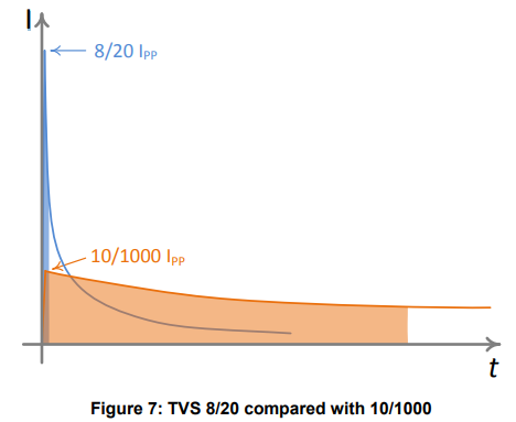
USB and high-speed data buses like HDMI may also require TVS protection. These connections
have multiple lines and run at high speed, so low capacitance is key to preserve data integrity. For
multiple data lines small packaging is critical to fit multiple devices into limited board area.

For high-speed data applications, devices such as the SE10P3F10U5.0MB offer low capacitance to
maintain signal integrity. The small DFN1006-3 package allows dual devices to be fitted into less
board space – ideal for high speed data pairs in USB 3.1.
About Semiware
Semiware has a comprehensive product lineup of circuit protection device products. The company leverages its technology in the semiconductor field and application background in end products to serve customers in the electronics, automotive and industrial markets.
If you have technical questions, please contact us as follows:
Email: ;
Tel: +86-21-3463-7654;
Toll-free technical support hotline: +86-400-021-5756
If you need to apply for samples or purchase products, please contact us as follows:
Email: ;
Tel: +86-18930674110;
Whatsapp: 008618123742225


Comments (0)